Industrial Vision Inspection Terminals: Cameras, Compute and Line Integration
Treating a vision inspection terminal as “a computer that runs a model” is the most common misunderstanding in these projects. A vision system on a production line is really a timing-critical system tightly coupled to the line: cameras are triggered, images must be processed within the takt time, and results must immediately drive reject or alarm actions. Any link that runs slow affects the output of the entire line.
Three Stages of a Vision System
Split it up and there are three: acquisition (the camera fires at a defined moment and forms an image, with lighting), inference (the image goes through the model and yields a result), and actuation (the result reaches the PLC over IO or a bus to drive reject, sorting or alarm).
Selection tends to fixate on the second stage (compute), but real project problems cluster in the first and third: trigger timing is wrong, images are blurred, or results never get out. So evaluate a terminal on what it offers at all three stages, not on a compute figure alone.
Camera Attachment: Interface, Bandwidth, Trigger
How cameras attach sets the acquisition ceiling. MIPI suits board-level direct connection at low cost, but cable runs are short and camera choice is limited. USB cameras are flexible and plug-and-play, but with multiple units you must check whether a USB controller’s bandwidth is being shared. GigE cameras allow long cable runs and good noise immunity, and are common on production lines.
More important than the interface is the trigger method: software trigger, or hardware trigger from an external sensor? Hardware triggering governs timing precision and jitter, which directly affects inspection consistency. That has to be settled at design stage together with camera and lighting — not tuned during integration.
Compute: Model Size and Takt Time Decide Together
Compute demand is not a fixed number; it comes from model complexity and permitted takt time together. The same model with half the takt time has entirely different compute and memory-bandwidth requirements. So two numbers must be explicit: the processing time allowed per image and the model size with input resolution.
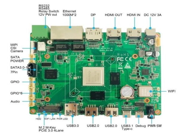
A model with higher compute and memory configuration, such as the 01B EDGE-RK3588-4D32 V1.2A, leaves more headroom with multiple cameras or larger models. If compute demand will rise as algorithms iterate, a module that can be added later, such as the RM182X M.2 2280 算力协处理器模组(20TOPS), lets the main controller avoid being specified at the top tier from day one.
Line Integration: IO, Communications, Interlocks
A result only matters if it gets out. Three common interfaces: digital IO (a simple, fast switch signal straight to the PLC), serial or Ethernet (Modbus, TCP and similar, carrying richer results), and host-system integration (writing results into MES or a database).
The critical point is that interface type and level must match the site’s PLC, with isolation where needed. A board with isolated IO and industrial serial, such as the 05A IPA-RK3588 工业控制主板, makes this integration easier — isolation avoids ground-loop interference, which is a real problem on lines dense with motors and drives.
Environment: Vibration, Dust and Lighting
Production environments are far harsher than offices: vibration affects connectors and camera mounting (a loosened connector is a classic source of intermittent faults), dust and oil mist degrade cooling and connector life, and changing ambient light directly affects image quality. The first two are solved by mechanical design and protection; the third usually needs dedicated lighting and shielding — stable illumination often improves results more than a better algorithm.
Selection Checklist
Five steps: fix the cameras (count, interface, resolution, hardware trigger or not) → fix the takt (processing time allowed per image) → fix compute and memory (from model and takt, with headroom) → fix integration (IO / serial / Ethernet, isolation required?) → confirm environment (vibration, dust, temperature, supply).
With camera count and interface, per-image time budget, model size and the PLC’s interface type written down, selection has a firm basis — far more reliable than comparing compute figures alone.