Robot and AGV Controller Hardware: Real-Time Layering, Fieldbuses and Compute Budget
Controller selection for AGVs, AMRs and service robots often starts with “how many TOPS do we need.” What actually decides whether a project lands cleanly is something else entirely: a mobile robot runs two kinds of tasks on wildly different time scales — motor control and safety response need deterministic, millisecond-scale reaction, while navigation, vision and task scheduling tolerate tens of milliseconds of jitter. Pushing both into one system without layering them is the single most common source of rework in projects like these.
A Controller Is Not “a Faster Computer”: The Two Classes Differ by Two Orders of Magnitude
Split the workload first. The real-time layer handles motor servo loops, encoder sampling, safety circuits and emergency stop. Its key metric is not “how fast on average” but “does it finish on time in the worst case” — a single missed deadline shows up as wheel jitter or a longer braking distance. The non-real-time layer handles SLAM, vision, path planning, communications and task scheduling. It wants throughput: more compute, more memory, a general-purpose OS and the standard open-source robotics stack.
The two pull the system in opposite directions. A general-purpose OS optimises for throughput through batching and caching, which is exactly what costs you response determinism. The familiar failure mode follows: a very powerful main SoC runs navigation and vision beautifully, but the motor control loop starts jittering under load — and that jitter is almost invisible on an unloaded prototype, surfacing only during continuous operation in the field.
Determinism Comes From Layering, Not Clock Speed
The robust approach is to separate the two layers: the main controller runs a general-purpose OS carrying the upper-layer algorithms, while the real-time part is delegated to an independent real-time unit (a microcontroller, or a co-processor with real-time extensions). The benefits are direct — if upper-layer software crashes, the safety layer keeps working; the real-time layer can have its own watchdog; the two layers can be upgraded independently. The cost is that you now have to design an inter-layer interface: UART, CAN or Ethernet, at what bandwidth and latency budget. That has to be settled at architecture stage, not discovered during integration.
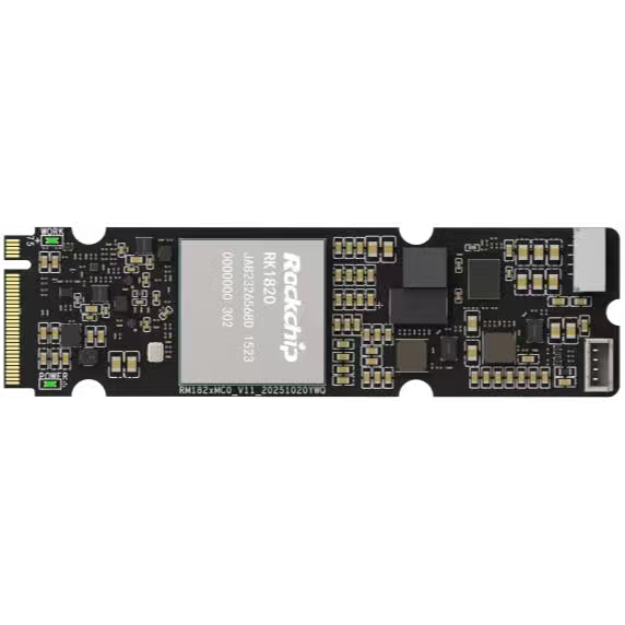
Compute deserves the same decoupling. Vision requirements on a robot keep rising as algorithms iterate, and if compute is welded to the main controller, every upgrade means a board swap. A module such as the RM182X M.2 2280 AI Compute Co-Processor Module (20TOPS) is valuable precisely because it makes compute an independently upgradable layer: the main controller is chosen for interfaces, determinism and reliability, and compute is sized to current algorithmic needs, neither forcing a compromise on the other. For products still iterating on algorithms, that headroom matters.
Fieldbuses and the Actuation Layer: CAN to the Drives, and Safety That Is Not Software-Only
The actuation layer is almost fixed by convention: motor drives and servos run over CAN, IO and some sensors over RS485 or serial, and industrial environments add isolation — common-ground noise and ground loops are the most stubborn interference sources in these systems, and they have to be dealt with at interface-design time, because retrofitting isolation later essentially means re-cabling.
What gets overlooked is the safety circuit. Emergency stops, bumpers and safety laser scanner outputs should not be treated merely as “one more software input.” Software hangs, misses interrupts, and is unavailable mid-update — precisely when safety functions matter most. Engineering practice should keep a hardware path that does not depend on software, able to cut motive power even if the main controller is dead. Prototypes usually ship with software-only e-stop because it is simpler to wire; adding it later, when a safety review demands it, is a far larger change.
Compute Budget: How Much for Navigation, Obstacle Avoidance and Vision
Splitting demand into three buckets beats asking “how many TOPS” in the abstract. Localisation and mapping mostly consume CPU and memory bandwidth, with point clouds and maps resident in memory. Vision-based avoidance and recognition is the NPU’s main workload. Sensor fusion and planning are sensitive to memory capacity and bandwidth — the most consistently underestimated item, since the data volume of multiple cameras plus point clouds dwarfs the model files themselves.
So alongside headline NPU throughput, look at memory configuration and bandwidth. When compute falls short, first confirm the algorithm is actually taking the hardware-accelerated path rather than silently falling back to general-purpose execution — that difference is often an order of magnitude, and far cheaper than moving to a bigger chip.
On-Board Conditions: Supply Fluctuation, Vibration and Power Loss
The biggest difference between a mobile platform and fixed equipment is power and mechanical environment. Battery voltage moves with state of charge and load, and transient sag during hard acceleration or emergency braking is significant — so the input range needs real margin rather than being designed to nominal. Vibration stresses connectors, heatsink retention and board mounting: a prototype that behaves perfectly on the bench starts showing intermittent contact after a few days bolted to a vehicle, which is an extremely common failure pattern.
On a mobile platform, power loss is not a controlled “graceful shutdown” — it happens whenever: a battery contact opens for an instant, an e-stop is hit, a charging contactor switches. Filesystem integrity, the flush strategy for critical data, and how watchdog and power-loss protection cooperate must therefore be designed in from the start, not deferred as “software will optimise that later.”
Form Factor, Thermals and Long-Term Maintenance
Vehicular equipment usually cannot use a fan — dust and vibration both cut fan life sharply, so heat has to leave through structure. That means the power budget must be computed for the worst case rather than typical load, and the thermal coupling to the chassis has to be designed together with it. Mounting (board-level, DIN rail, wall) should likewise be fixed during vehicle design, or it ends up solved with improvised brackets.
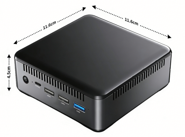
Finally, long-term maintenance. Robot deployments arrive in batches and keep expanding, so supply continuity of the controller platform, mechanical stability of the form factor, and the spares strategy directly drive operating cost for years afterwards. Where the actuation interfaces and reliability requirements are already clear, an industrial control board such as the 05A IPA-RK3588 Industrial Control Board matches better on interface completeness and environmental ratings; where compute demand is moderate and size plus power draw matter, an edge-computing form factor like the 02A EDGE-RK3576 V1.1 leaves more room.
Reverse the order and selection gets much clearer: layer first, then fix the interfaces, then size compute, and only then pick the silicon. Starting from the chip makes it easy to leave holes in determinism and safety that cannot be patched later.