Wide-Temperature Industrial Design: Components, Thermal and Validation from -40 to 85 C
“The SoC is industrial grade, but the board still fails the temperature spec” — a very typical rework in industrial projects. The cause is usually not the SoC but the supporting cast: capacitors, crystals, storage and connectors are the real barrier in wide-temperature design.
The SoC’s rating is not the board’s rating
The temperature range on a chip datasheet is often junction temperature, or ambient under a specific thermal condition. Put the same SoC in a sealed metal enclosure inside an outdoor cabinet in summer and the actual junction temperature may run twenty or thirty degrees above ambient. So the first step is converting the ambient requirement into a junction temperature budget, then checking whether the thermal design can hold it.
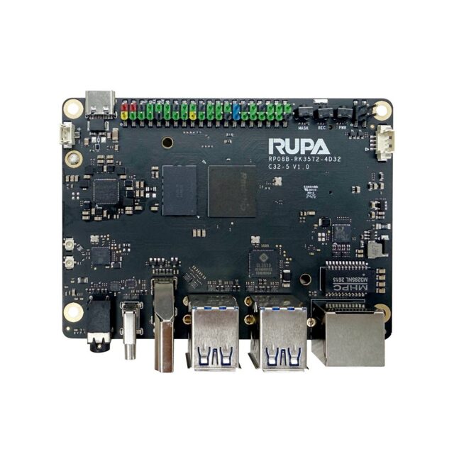
This is why a board’s wide-temperature capability depends heavily on thermal design rather than SoC choice. Industrial boards such as the 05A IPA-RK3588 industrial control board treat the thermal path, component temperature grades and enclosure interface as one problem rather than simply swapping in a wide-temperature SoC.
Cold fails at startup; heat fails over time
These two directions have entirely different failure mechanisms, and the validation methods must be separated accordingly.
At low temperature the risk concentrates in the startup moment: the equivalent series resistance of electrolytic capacitors rises sharply tens of degrees below zero, causing supply ripple and power sequencing problems; crystals struggle to start or drift in frequency, potentially preventing the SoC from booting at all; some storage devices fail to read. Many devices sit happily in a cold chamber for two hours and then fail on a cold start — that is exactly this mechanism.
At high temperature the problem is continuous: leakage rises, components age faster and data retention degrades. One easily overlooked point — the data retention time of eMMC-class storage shortens dramatically as temperature rises, so logs or configuration stored for years at eighty-five degrees can suffer silent corruption. Any 24/7 device needs this factored in.
Component categories to watch
First, capacitors. Ordinary aluminium electrolytics are the number one enemy of wide-temperature design; polymer or ceramic types are the fix. The unit price is higher, but the saved rework cost dwarfs the difference. Second, crystals: confirm an industrial or at least wide-temperature part and verify load capacitance matching. Third, memory and storage: industrial temperature grades are mandatory, and their price and lead time differ greatly from consumer grades, so lock the part early. Fourth, connectors and cabling: plastics become brittle in the cold and may crack after a few mating cycles.
Thermal paths beat fans for reliability
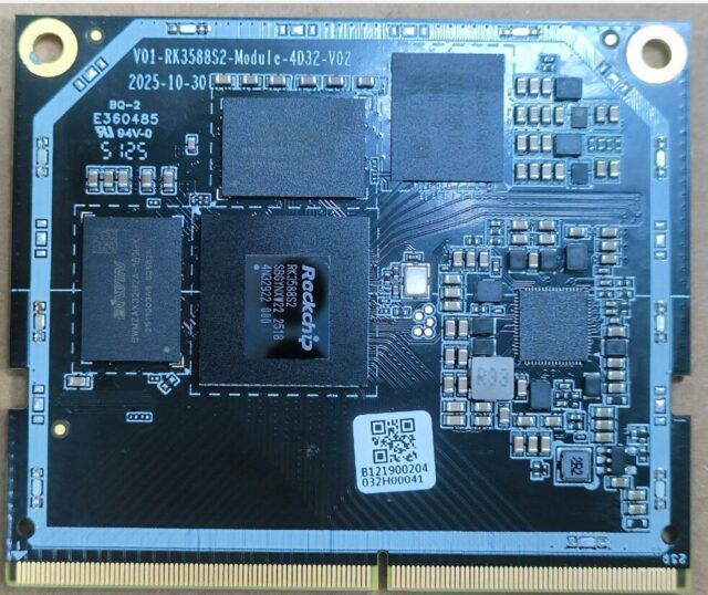
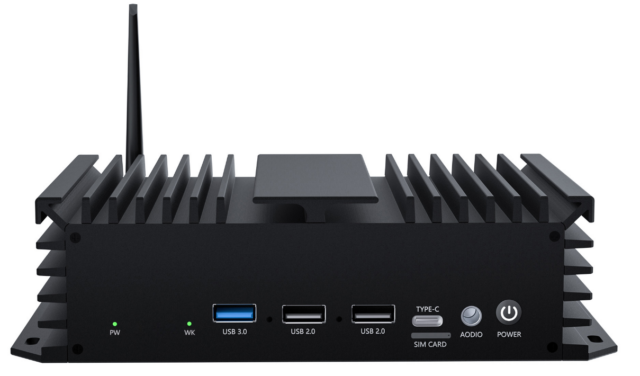
Industrial sites generally do not want fans — bearing life is finite, they clog with dust, they make noise, and a fan is itself a failure point. The key to fanless design is conducting heat into the enclosure: the SoC couples to the metal housing through a thermal pad or grease, and the housing acts as the heatsink. The trade-off in options such as the 03R EDGE-RT28 (RK3528) industrial router board and the 01M M-RK3588S system-on-module lies precisely in balancing power dissipation against available surface area.
If a fan is unavoidable, use closed-loop temperature control and monitor fan speed in firmware, reporting anomalies rather than silently continuing.
Validation: constant-temperature soak is not enough
Two hours at high and low temperature only proves the board runs at a constant temperature; it does not prove long-term viability. What actually earns its keep is thermal cycling: switching repeatedly between minus forty and eighty-five degrees for a hundred cycles or more. Cycling stresses solder joint fatigue, connector contact and mismatched thermal expansion between materials — precisely the dominant sources of field failure, and precisely what soak testing cannot detect.
Two further tests are commonly skipped. One is cold start: powering up from fully cold rather than from a board already running inside the chamber. The other is condensation: moving a device from a cold environment into warm humid air forms dew on its surfaces and can short-circuit it without conformal coating. Run at least one combined thermal shock plus humidity cycle.
Conclusion
Wide-temperature design is a system problem: convert ambient into a junction budget, verify temperature grades category by category, prefer a fanless conduction path, and validate by thermal cycling rather than soak. Ask the supplier at selection time for an industrial-grade BOM and a thermal cycling report — far cheaper than rework later.