Designing a SoM Carrier Board: Power, Clocks and Routing for SO-DIMM Modules
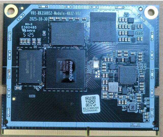
Building a product on a system-on-module means handing the hardest parts — SoC, memory, storage — to the module vendor and designing only a carrier board. That saves months of high-density routing work, but a carrier board has its own places where shortcuts are not an option.
Why SO-DIMM is a good choice
The 01M-M-RK3588S SoM routes every functional interface of the RK3588S out to a DDR4 SO-DIMM connector. SO-DIMM is a mature standard part — easy to source, easy to mate — and the carrier board can be built with ordinary processes, without handling BGA assembly or high-speed signal integrity yourself. That is precisely the value of the module approach.
Leave real headroom in the power design
The first thing to get right on a carrier board is power. Platforms like RK3588S have multiple supply rails and power-up sequencing requirements. A common failure is selecting DC-DC parts against typical power draw; at measured peak the margin is gone and the symptom is random reboots or instability under load. Size for peak draw with at least 30% headroom, and confirm the rail sequencing matches the module requirement.
Clocks and reset
For interfaces needing an external clock, choose crystal accuracy and load capacitance to the module specification rather than reusing parameters from an older project. Reset signals need adequate width and must tolerate jitter at power-up. These details may look fine on a prototype and only surface in production — often batch-dependent.
High-speed signals and interface placement
Some parts of the carrier board still need impedance control: USB 3.0, HDMI, Ethernet differential pairs. Keep traces short, keep reference planes continuous and match differential pair lengths. Interface positions should follow the mechanical design, not routing convenience — otherwise connectors end up somewhere awkward to assemble.
If the project still needs to validate algorithms first, run it on a finished single-board such as the 01A RP01A-RK3588S-5D32 or 01B EDGE-RK3588-4D32 V1.2A, then move to a module design for production. Align interface definitions early and the transition is smooth.
When not to use a SoM
If nobody on the team has done DDR routing and impedance control, the hidden cost of a module approach will exceed expectations. If expected volume is small, carrier board development is hard to amortise. In both cases, a finished single-board or mini PC form factor is the better deal. Specifications are on the 01M-M-RK3588S product page.